

The importance of measuring the distribution of vertical forces per wheel in static conditions for maintenance
For any type of vehicle, a correct load distribution exerted by its contact points on the ground is one of the fundamental requirements for optimal static and dynamic behaviour.
In the case of a railway vehicle, an even load distribution is essential for safety and running quality.
Let’s consider the bogie scheme below:
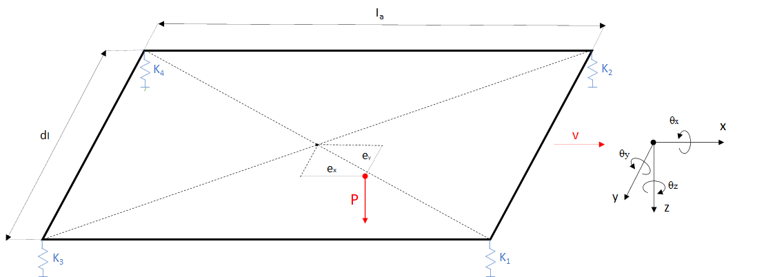
The main influence factors on the load distribution are essentially three:
- Stiffness of the primary suspension at each wheel
- Coplanarity of the contact points with the track
- Eccentricity of the load
The ideal condition for a bogie is:
- primary suspension springs in perfect condition and with the same stiffnesses;
- perfect coplanarity of the 4 contact points with the track;
- load on the geometric centre of gravity (without eccentricity).
When a single factor deviates from the ideal condition, it affects the load distribution. In particular, if there is an alteration of the springs of the primary suspension that leads to different stiffnesses, the load distribution exerted by the wheels will be different and the load on the two diagonals of the bogie will always be unbalanced. If ‘’Fi’’ are the forces exerted by each wheel, it results in (F1 + F4) ≠ (F2 + F3).
Similarly, if there is no coplanarity of contact points due to twisted tracks or bogie frame deformation, the diagonals will also be unbalanced.
The non-coplanarity of the contact points also occurs when the four wheels are not evenly worn. During the measurement of the wheel load distribution, this latter condition is often more difficult to verify than twisted tracks or twisted bogies, also due to wheel accessibility.
Unlike the other two cases, the presence of eccentric load does not affect the difference between the two diagonals if the other two ideal conditions are verified, ensuring (F1 + F4) = (F2 + F3). On the other hand, a load that is not perfectly centred in the geometric centre of gravity involves different vertical loads:
F1 ≠ F2 ≠ F3 ≠ F4.
To easier understand the behaviour of a railway bogie, an analytic model was created in order to interact, change parameters and verify how these variations affect the wheel loads.
Below you can find a link to access a platform called Bogie Playground:
BogiePlayground (powerve-156508.web.app)
Why is correct load distribution important?
For wheeled vehicles, in particular for railway vehicles, the load distribution mainly affects two phenomena:
- Acceleration / braking phase
- Running safety on twisted tracks
As regards the first phenomena, specifically the braking phase: when a braking torque is applied to a railway axle, the system of forces acting on the single wheel can be represented as follows:
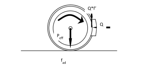
where:
Peff = vertical load on the wheel;
Q = radial force exerted by the braking element;
f ’ = friction coefficient;
fad = wheel-rail adhesion coefficient;
On the contact surface, between the braking element and the wheel, a friction force opposite to the sliding force between the two elements arise, which is:
Fa = Q*f’
This frictional force generates a torque of opposite direction to that of the motion and of a magnitude equal to the product Fa*r, with “r” radius of the wheel.
To remain in a macro-adhesion regime, the adhesion force to the wheel-rail interface should remain greater, or at least identical, to the force exerted by the braking element, i.e.:
Fa ≤ fad*Peff
Therefore, an uneven distribution of the load, which results in a variation of Peff of the single wheel, for the same braking force acting on the entire wheelset, can lead to a slip of one of the two wheels. This circumstance would result in an unwanted yaw effect on the bogie.
We have briefly seen how an uneven wheel load distribution would affect the braking phase of a railway vehicle. The same can be said for the acceleration phase.
Let’s now see how an imbalance of vertical forces affects the running safety when running on twisted tracks.
In general, running safety is guaranteed when the wheel-rail interaction forces remain within certain limits that prevent vehicle derailment or permanent deformation of the track.
Specifically, a railway vehicle is in a risky condition when the wheel flange comes into contact with the rail. In this case it is necessary to consider the Y / Q ratio between the transverse force exerted by the wheel on the rail (Y) and the vertical load of the wheel (Q).
In fact, due to the force Y and the friction coefficient at the contact point, the wheel tends to change the axis around which it rotates. The new axis will be orthogonal to the contact surface and will pass through the contact point between the flange and the rail. In this new condition the wheel tends to lift but it is the weight force Q to oppose. So, any cause that may involve a decrease in the vertical wheel load can cause an increase in the Y / Q ratio and therefore an increase in the risk of derailment.
One of the most significant track defects that can pose a safety hazard is the twist.
The definition of the twist (g defined in thousandths) is the variation along the rail axis of the vertical slope and is expressed as the ratio between this vertical difference h over a longitudinal reference distance d (usually wheelbase or bogie centre distance):
g (‰) = h/d
The twist represents the most common cause of derailment since, in general, its presence alters the wheel load distribution, leading to load imbalance.
Once a certain critical value has been exceeded, the vehicle wheel first tends to decrease part of its weight, then to rise, triggering the overlap of the flange on the top of the rail, finally the derailment of the rolling stock.
A correct, and therefore balanced, distribution of the vertical forces per wheel of a vehicle means that it is more capable of adapting to track irregularities.